1.3.2. Programming the FPGA
After the installation of Vivado, we will have to clone the FPGA repository and edit an existing project for our “Hello World” (Blink) project.
1.3.2.1. Clone FPGA GitHub repository
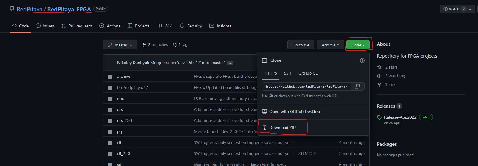
Go to the Red Pitaya FPGA Github site and download the ZIP folder of this project.
If you are using Windows, download the project repository and extract it to a folder of your choice. Remember the path to the location of the extracted repository (when you will be searching for your disk location in the WSL, go to the root directory and move into the mnt directory).
Alternatively, if you are using Linux or WSL, you can first install git, then move to a desired location and make a clone of the Red Pitaya Git repository:
sudo apt-get install git
git clone https://github.com/RedPitaya/RedPitaya-FPGA.git
1.3.2.2. Make an FPGA project
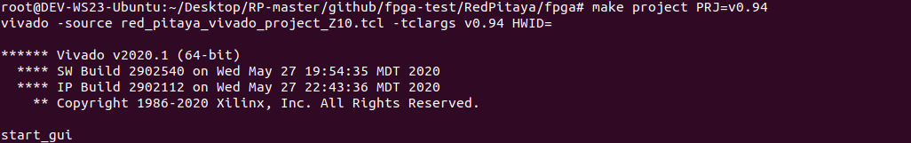
Go to the downloaded ZIP location and extract it. Now open Vivado and using the TCL console navigate to the extracted folder and make a Vivado project.
cd Downloads/
cd RedPitaya-FPGA/
. /opt/Xilinx/Vivado/2020.1/settings64.sh
make project PRJ=v0.94 MODEL=Z10
Note
In order to open a project for models SDRlab 122-16 or SIGNALlab 250-12, you need to specify MODEL=Z20 (SDRlab) or MODEL=Z20_250 (SIGNALlab) as a parameter.
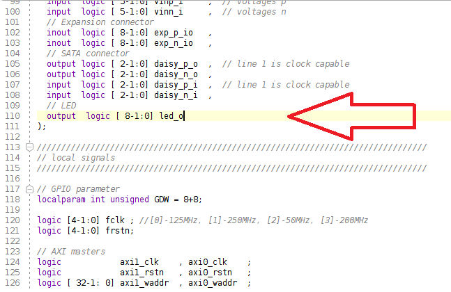
For this project, you will only have to edit the red_pitaya_top.sv file. Edit the port led_o assignment at the beginning of the file. Change the port to output logic.
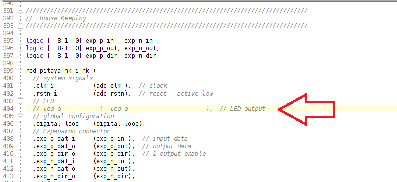
Now, in this section of the file, comment out the led_o port.
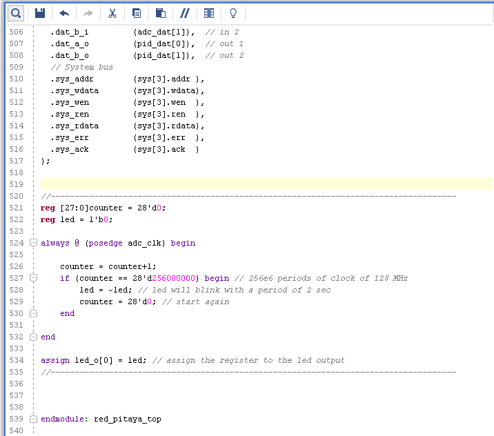
Finally, insert this code at the end of the module, before endmodule: red_pitaya_top. It will make the LED blink.
reg [27:0]counter = 28'd0;
reg led = 1'b0;
always @ (posedge adc_clk) begin
    counter = counter+1;
    if (counter == 28'd256000000) begin // 256e6 periods of clock of 128 MHz
        led = ~led; // led will blink with a period of 2 sec
        counter = 28'd0; // start again
    end
end
assign led_o[0] = led; // assign the register to the led output
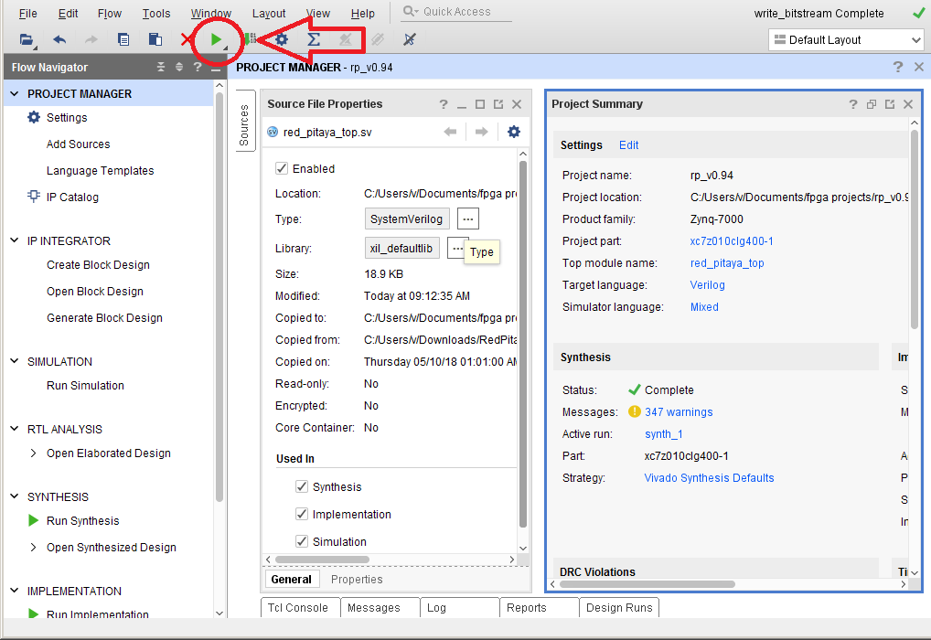
Now you have to start synthesis, implementation, and writing a bitstream. Press the button to start the synthesis. You can also just click on the “Generate bitstream” and all the steps will execute automatically.
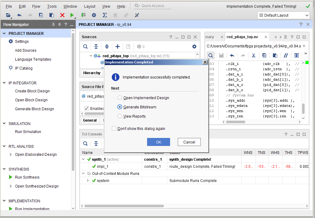
After synthesis is finished, start implementation.

Implementation finished. Start writing the bitstream.
The bitstream file red_pitaya_top.bit is located in …/prj/v0.94/project/repitaya.runs/impl_1
You have to send this file to your Red Pitaya board. Open a terminal and connect to your Red Pitaya using an SSH connection. Also, enable the read/write operation on the Red Pitaya.
ssh root@your Red Pitaya IP
redpitaya> rw
Open Terminal and go to the .bit file location.
cd Downloads/RedPitaya-FPGA/prj/v0.94/project/repitaya.runs/impl_1
Send the file .bit to the Red Pitaya with the scp command.
scp red_pitaya_top.bit root@your Red Pitaya IP:/tmp
Now establish an SSH communication with your Red Pitaya and check if you have the copy red_pitaya_top.bit in the tmp directory.
redpitaya> cd /tmp
redpitaya> ls
Load the red_pitaya_top.bit to xdevcfg with
redpitaya> cat /tmp/red_pitaya_top.bit >/dev/xdevcfg
Congratulations, the LED should now be blinking, and the project should be running on the FPGA.